New cleanrooms for
Electron-Beam nanoLithography (EBL)
based on Scanning Electron Microscope (SEM)


Documentation

Building

Public opening


Documentation


Outlook of the laboratory (version 0530 = MMDD):


A grid of 0,5 meter pitch on background of this as well as of some other drawings.

Room types:
- class   100 : space for the EBL column (temperature stabilized to +/-0,5°C), space "1b" (exhaust of 1200m3/hour),
- class   1000 : other parts of the cleanroom "1a",
- class  10000 : area "1c", area "1d" (exhaust of 2400m3/hour)


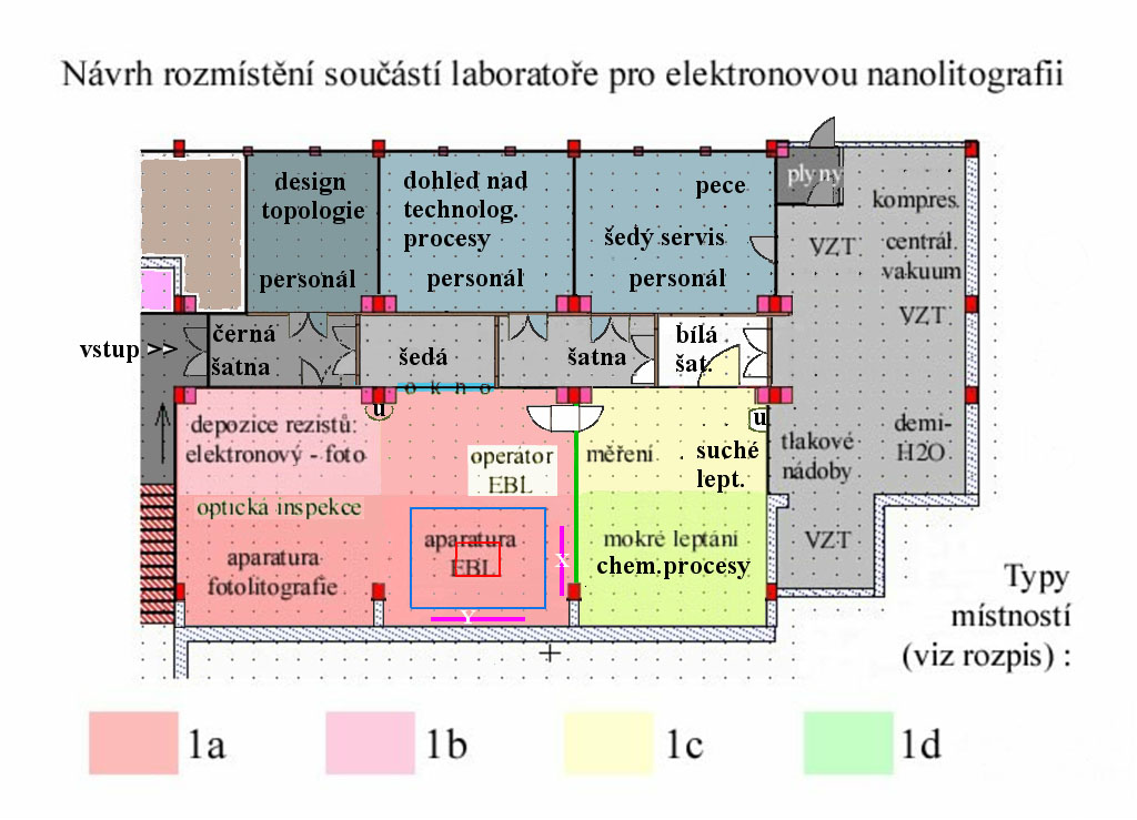
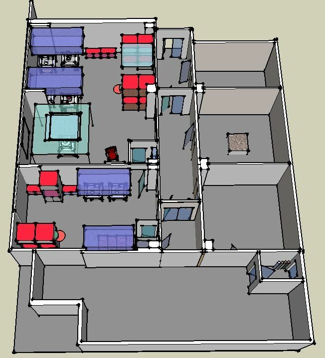
Position of (enumerated) parts of the laboratory (version 0703):

Labeling (and characteristics) of individual rooms:
room No.F39 - "black" office (staff - topological design of structures),
room No.F40 - "grey" office (staff - technological processes supervision),
room No.F41 - "grey service" (staff - maintenance, part of technological equipment),
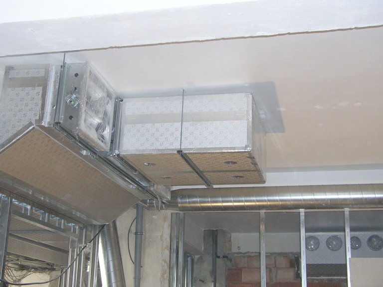
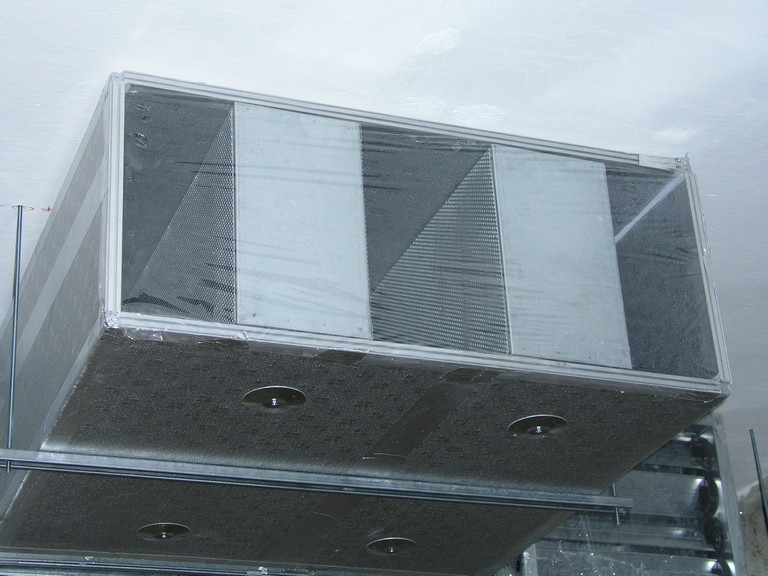
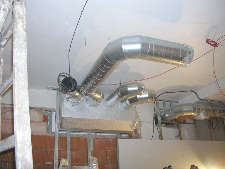
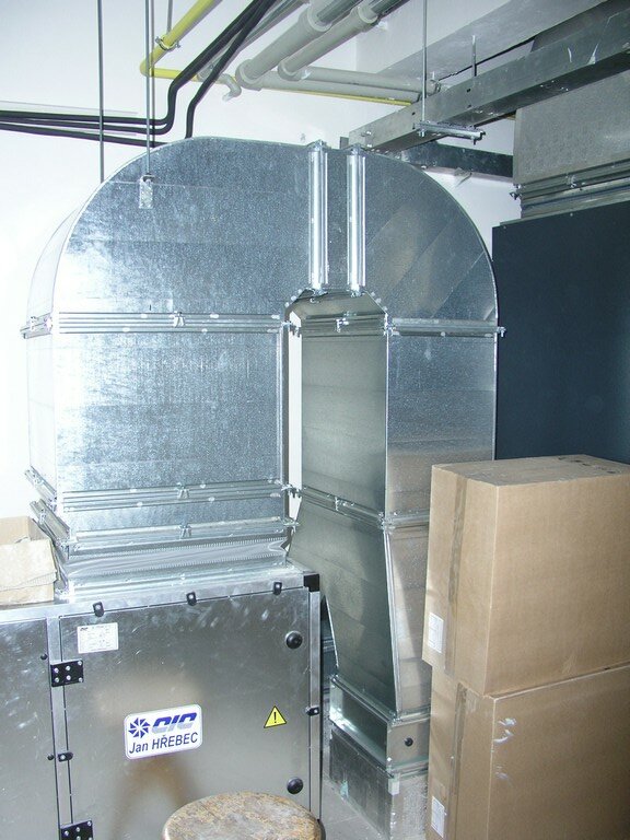
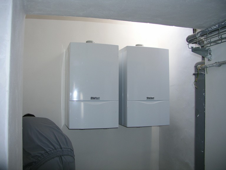
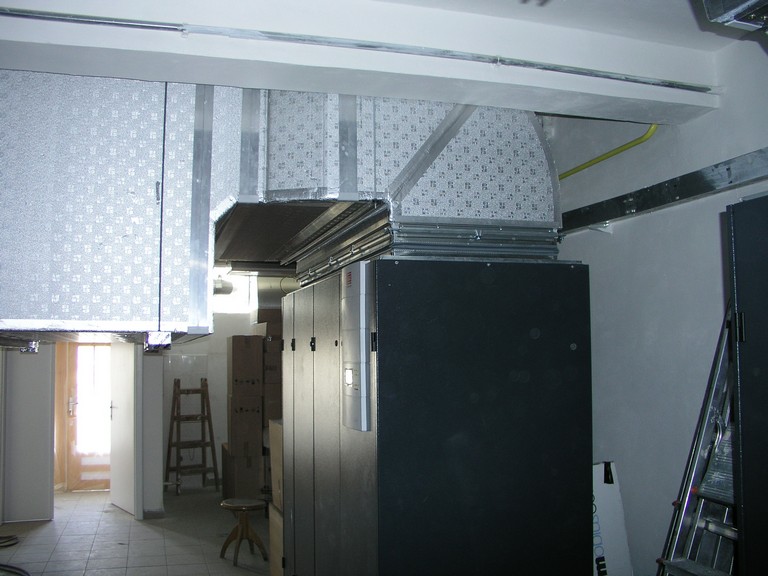
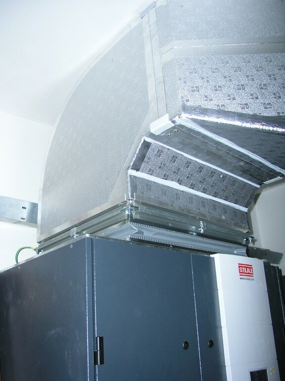
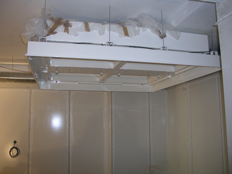
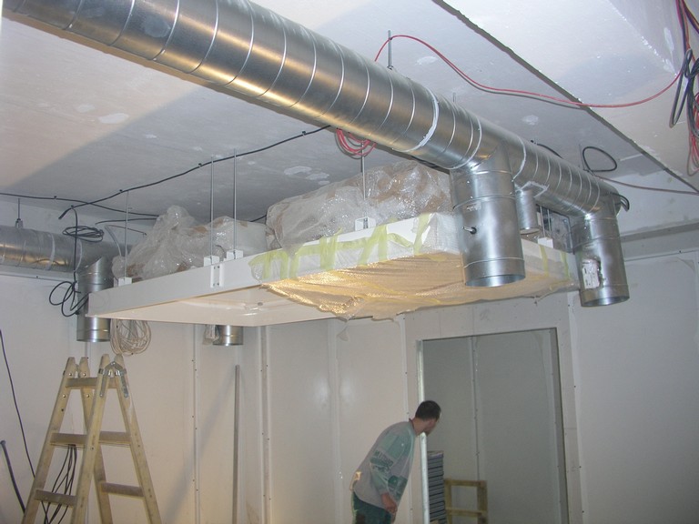
room No.F42 - "grey" room (HVAC, part of technological equipment),
room No.F43A - "black entrance" (entrance area),
room No.F43B - "grey gowning area" (first gowning),
room No.F44 - "white gowning area" (final gowning),
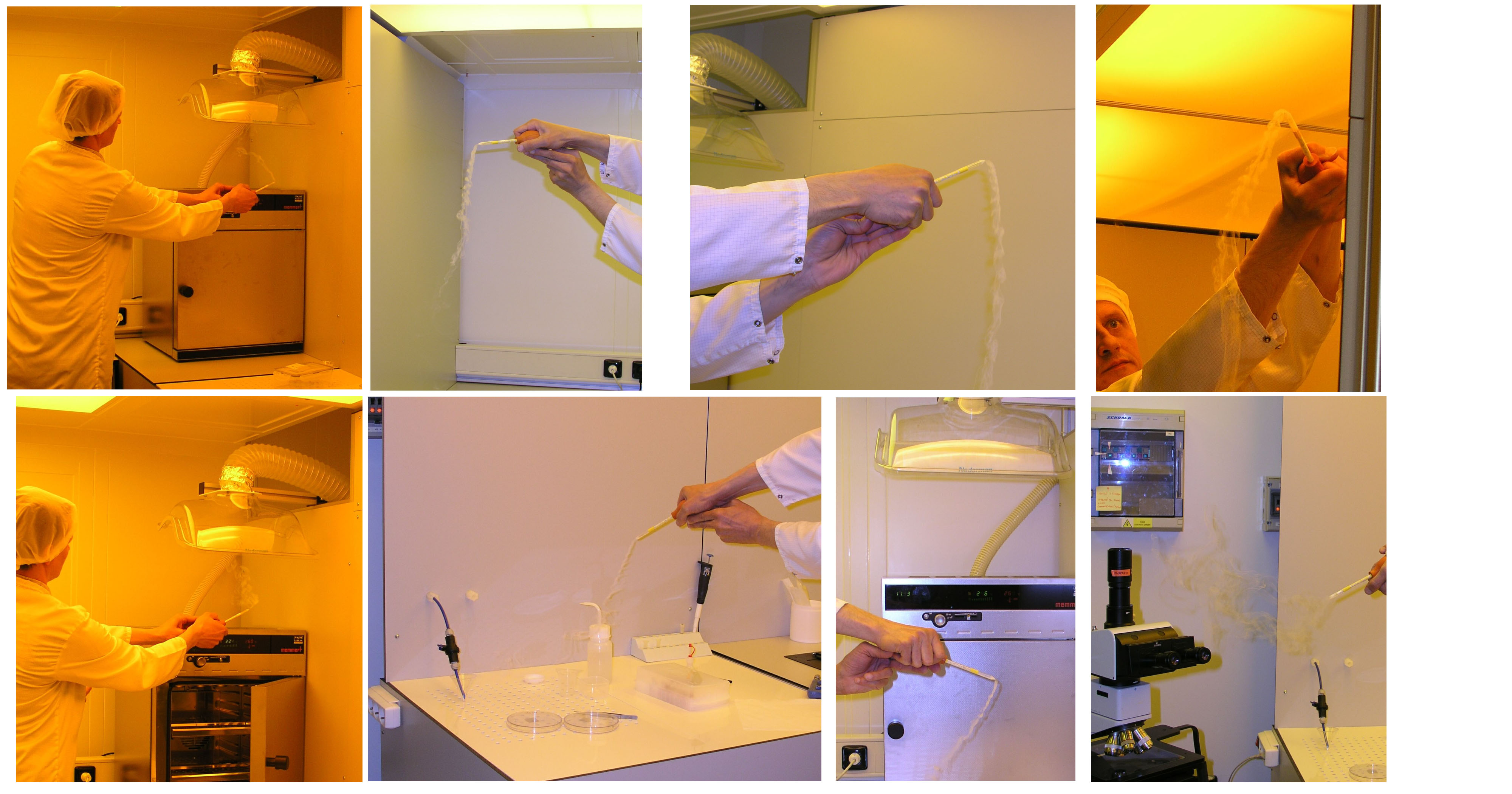
room No.F45 - cleanroom of class 10000 (wet- and dry- etching),
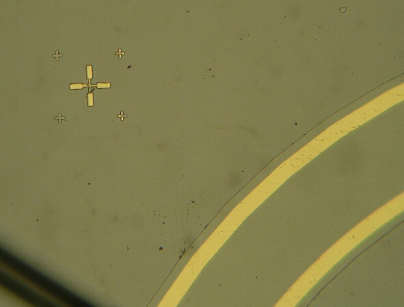
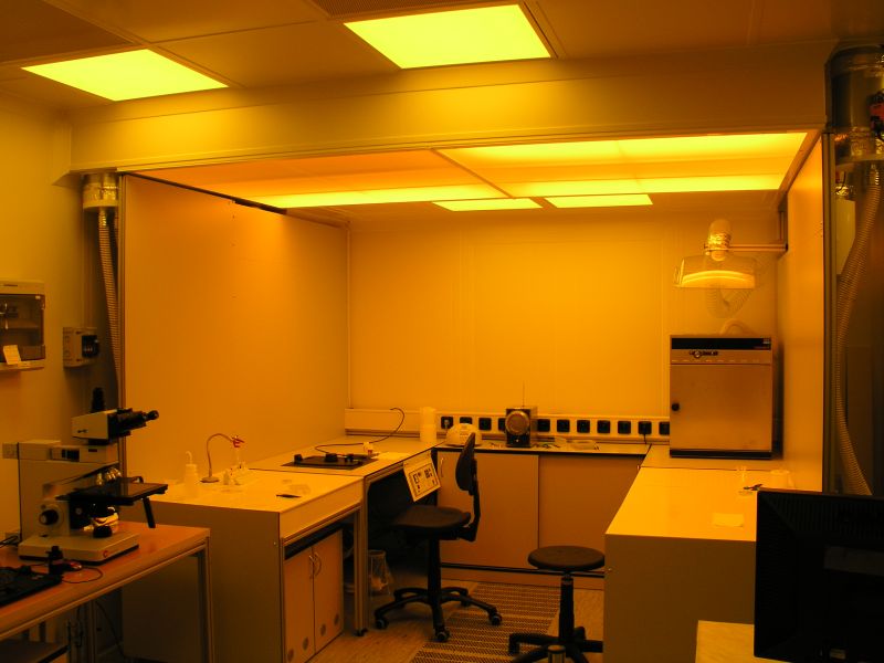
rooms No.F46+F47 - cleanroom of basic class 1000 comprising zones of class 100 (lithography)


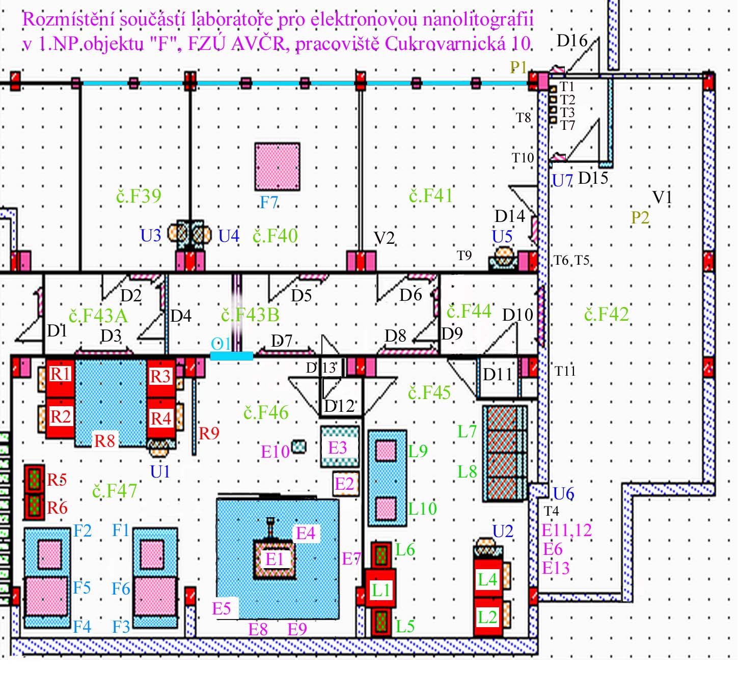
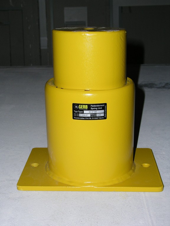
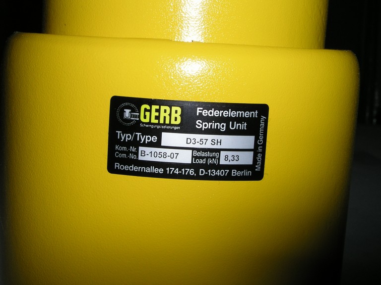
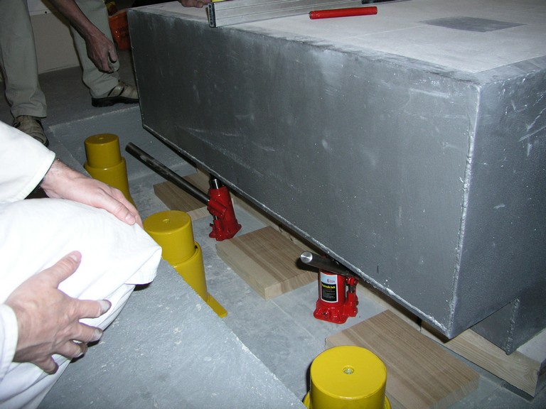
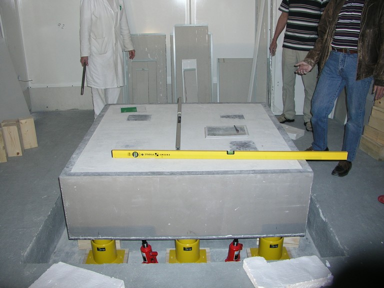
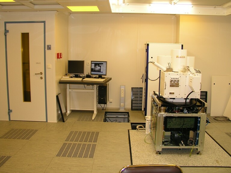
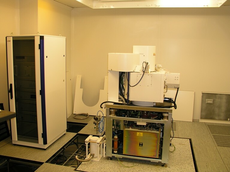
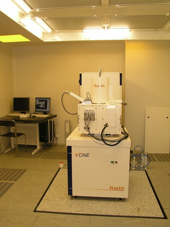
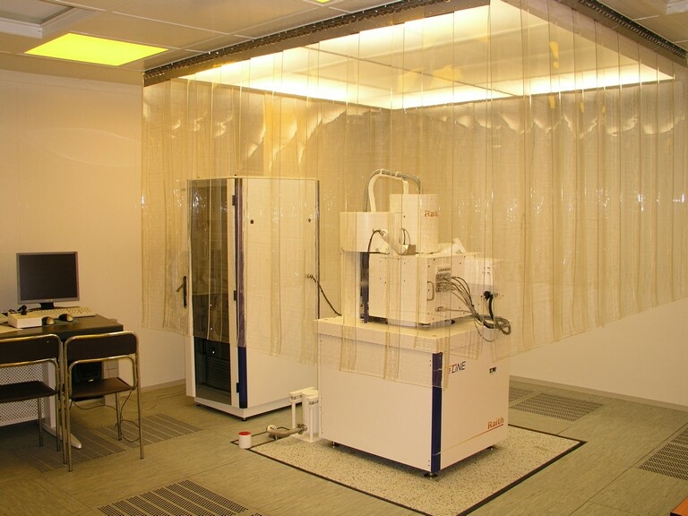
Area of electron-beam lithography + microscopy (EBL/SEM): 
E1 - basic unit (column)
E2 - rack comprising supply and control units
E3 - control panel EBL/SEM
E4 - antivibrational block (for EBL/SEM)
E5 - laminar zone (+/-0,5°C, class 100)
E6 - roughing pump
E7 - coil X (of spurious magnetic fields compensation system)
E8 - coil Y  (   - " -   )
E9 - coil Z   (   - " -   )
E10 - EBL/SEM operator seat
E11 - EBL/SEM system thermostat unit
E12 - unit of electron lens thermostat (stabil. to 0,1°C)
E13 - EBL/SEM control UPS
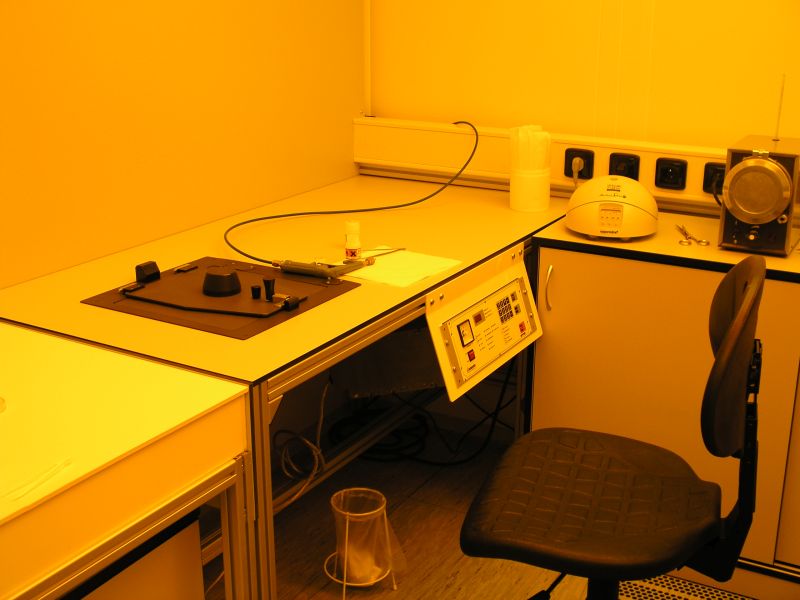
    Area of resist processing (room No.F47): 
R1 - chemical flowbox (electron resist deposition)
R2 - chem.flowbox (electron resist development)
R3 - chem.flowbox (photoresist deposition)
R4 - chem.flowbox (photoresist processing)
R5 - box for resists (exhausted)
R6 - box for developers, etc. (exhausted)
R7 - storno
R8 - laminar-flow area, class 100
R9 - anti-static curtain
     
Photolithography and optical microscopy area (room No.F47): 
F1 - hanging laminar-flow unit (optical microscope)
F2 - hanging laminar-flow unit (diagnostics)
F3 - hanging laminar-flow unit (contact aligner)
F4 - hanging laminar-flow unit (projectional aligner)
F5 - antivibrational block (for contact aligner)
F6 - antivibrational block (for projectional aligner)
    Wet- a dry- etching cleanroom (room No.F45): 
L1 - fume hood (corrosionless construction)
L2 - chemical flowbox (wet etching - acids, bases)
L3 - storno
L4 - chemical flowbox (wet etching - organics)
L5 - box for anorganic chemicals (exhausted)
L6 - box for organic chemicals (exhausted)
L7 - dry-etching equipment (PE)
L8 - dry-etching equipment (RIE)
L9 - hanging laminar-flow unit (optical microscope)
L10 - hanging laminar-flow unit
     
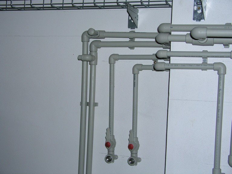
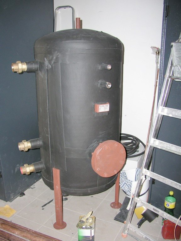
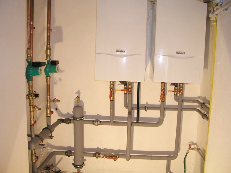
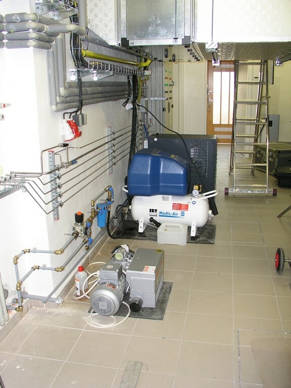
Technical background (rooms No.F41 and F42 - HVAC): 
T1 - compressed gas (O2)
T2 - compressed gas (CF4)
T3 - compressed gas (spare position)
T4 - equipment for pure water preparation
T5 - oil-free compressor
T6 - pump and central vacuum-reservoir
T7 - compressed gas (forming gas Ar+5%H2)
T8 - oven
T9 - die saw
T10 - thin-layer deposition equipment
T11 - LN2 -> gaseous nitrogen generator
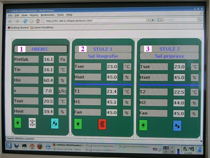
    Some other parts: 
F7 - antivibrational block (room No.F40)
O1 - check-window to the cleanroom No.F46
P1 - heating gas input valve (on the outer wall)
P2 - gas-heating for the input HVAC unit
U1 - washer incl. safety shower (room No.F47)
U2 - washer incl. safety shower (room No.F45)
U3 - washer in room No.F39
U4 - washer in room No.F40
U5 - washer in room No.F41
U6 - washer + sink in room No.F42
U7 - washer + sink in room No.F42 (maintenance)
V1 - HVAC units (according to the HVAC design)
V2 - main computer for HVAC measur.&control


Complete list incl. other parts and equipment (in Czech) here


Drawings of individual technological layers (version 0530):
1 - HVAC tubing,
2 - cooling circuits,
3 - circuits of demineralized water for technology,
4 - outlook of tap-water and sink system,
5 - piping for gaseous nitrogen and compressed air (oil-free),
6 - electrical installation system,
7 - recommendation from preliminary measurement of vibrations and strain magnetical fields in the area of the new laboratory (in Czech). Notice: position "2" referred to in the text corresponds to the position of the item # E1 in the above presented drawing. Full text (in English) of the measurement Protocol here.

Comments (in Czech) to the drawings here.


Operational Rules (in Czech) for the laboratory here.

List (in Czech) of technological operations and chemicals used here.


"Quasi-3D" aerial views of the laboratory (the door D10 and some other details are not shown in these views):


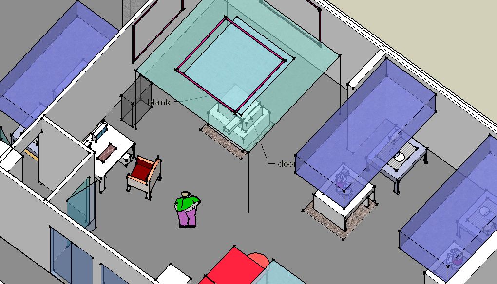
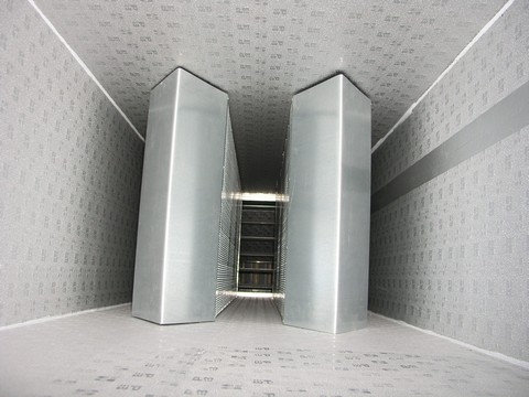
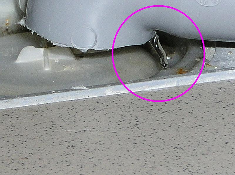
Orientation of the central EBL unit vs the beam blanker


Technical description of equipment for active compensation of magnetic fields available here for types: SC12, SC20.


Building

Fabric


Building insulation:
-sound protecting,
-against moisture,
-thermal:
-of the floor,
-of the walls

Air-conditioning lines installation:
   -ducting:
-recirculation,
-input,
-exhaust,
   -silencers:
-of recirculation,
-of output,
-of input
   -laminar zones,
   -double floor

AC units:
-transport,
-input of the unit #1,
-output of the unit #2, the unit #3,
-heating,
-cooling
-dehumidification

Anti-vibration blocks:
-E4:
-the well,
-the fundament steelfixing,
-concreting of the block,
-isolation units installation,
-preliminary measurement of the E4 block vibrations,
-complex measurement on the block E4,
-final adjustment

-F5+F6:
-the fundament steelfixing,

-F7:
-the fundament,
-the block steelfixing

Cleanrooms building:
-the room c.F46/47 -installation,
-white gowning area c.F44 -installation,
-grey changing area c.F43B -installation

EBL-tool:
-transport,
-installation


Building process related to some parts of the laboratory
(see captions of individual thumbnails displayed):

the room c.F46/47

 
c.F46 room - the well of E4

  
the room c.F46/47

 
c.F46 room - the well of E4

  
concrete fundament in c.F45-47

 
the well E4 bottom

  
view from SW corner of c.F47

 
view from c.F44

  
air-recirculation trenches in c.F42

 
isolation of the E4 well

  
the edge of the air recirculation trench

 
SE corner of c.F42

  
view from SE corner of c.F45

 
view from c.F43A - the main air-recirculation trench

  
the fundament steelfixing for the blocks F5, F6

 
the fundament steelfixing for the antivibrational block E4

  
the steelfixing for the fundament F7

 
view from c.F44 - the area of the main air-recirculation channel

  
the main drain-tubing outlet

 
drain-tubing in c.F41

  
isolation of the edge of the recirculation trench c.F45

 
the floor of c.F45-47 before application of thermal isolation

  
detail of thermal isolation

 
the floor adapted for concrete application

  
the edge of the air-recirculation trench of c.F47

 
air-recirculation trench of c.F45 before concrete application

  
air-recirculation trench of c.F47

 
final concrete surface of the lower floor of c.F46-47

  
drain-tubing outlet

 
the main air-recirculation trench, view from c.F42

  
the air-recirculation trenches at the room c.F42

 
laying of the main air-recirculation line, view from the room c.F44

  
contamination protection of the recirculation tubing during manipulation

 
laying of the main recirculation line, view from the room c.F43A

  
air-recirculation flues of the room c.F47

 
air-recirculation flues of the room c.F46

  
air-recirculation tubing at the room c.F42

 
the ceiling of the room c.F47 prepared for concreting

  
the outer part of the ceiling of c.F47 prepared for concreting

 
concreting of the floor above the recirculation line of c.47

  
concreting of the floor of the machine-room c.F42

 
air-recirculation flues of the room c.F45 comprising silencers

  
the F7 antivibrational block well under preparation

 
facing of the walls of the machine-room c.F42

  
the F7 antivibrational block well

 
building of the partition walls of the machine-room c.F42

  
feed-throughs in the partition wall as viewed from the machine-room c.F42

 
the same feed-throughs in the partition wall viewed from the room c.F45

  
concreting of the antivibrational block F7 fundament

 
facing of the ceiling and the walls of the machine-room c.F42

  
building of the F7 block well

 
installation of electric lines

  
the F7 block well

 
thermal isolation of the walls of the cleanrooms c.F46/47

  
northern side adjacent to the machine-room c.F42

 
thermal isolation of the walls of the cleanrooms c.F46/47

  
the main air-input tubing split to c.F46-F47

 
the area prepared for the exhaust tubing from R1-R4

  
the input tubing to c.F46-F47 - view from c.F43A

 
the input tubing ro c.F46-F47 - view from c.F44

  
regulation elements on the main air-input tubing

 
input-air flues to c.F46

  
adjusting of the position of the E4 block steelfixing

 
adjusting of the position of the E4 block steelfixing

  
fundament for the concreting of the block E4

 
concreting of the block E4

  
the steelfixing of the block F7

 
the fundament of the block F6

  
building of the cleanroom c.F46

 
building of the cleanroom c.F47

  
building of the cleanroom c.F46

 
building of the cleanroom c.F47

  
northern side adjacent to the machine-room c.F42

 
the feedthroughs for the air-input and exhaust tubing to c.F45

  
the area of the northern gate

 
building of the cleanroom c.F46

  
building of the cleanrooms, view from c.F43A

 
the position of the feedthrough in the wall c.F45-c.F46 for the interconnection E1-E6

  
tubing and lines, view from c.F47 (upper part)

 
tubing and lines, view from c.F43A

  
tubing and lines, view from c.F47 (lower part)

 
tubing and lines, view from c.F40

  
input-air tubing comprising the silencer (for the laminar zone E5)

 
the input-air silencer (for the laminar zone E5)

  
transport of AC units

 
transport of AC units

  
transport of AC units

 
the area around the northern gate

  
western wall of the machine-room c.F42 - 1n

  
the northern gate

 
western wall of the machine-room c.F42 - 3s

 
western wall of the machine-room c.F42 - 2c

 
southern wall of the room c.F43B - 1e

 
southern wall of the room c.F43B - 2w

  
the white gowning area c.F44

 
the air-input into the cleanroom c.F47

  
exhaust tubing from L2+L4 (left) and L1 (right)

 
exhaust tubing from R1-R4

  
the steelfixing of exhaust tubing output

 
exhaust tubing from R3-R4

  
isolation of the ceiling edge of c.F45-47

 
concreting of the exhaust tubing output

  
concreting of the ceiling edge of c.F45-47

 
the northern gate area

  
adjusting of positions of the AC units #2,#3

 
the AC unit #2 adjusted over its air-recirculation tubing

  
the AC unit #1 fan

 
a flange gasket

  
the feedthrough for work media tubing at c.F45

 
the AC unit #3 air-filter chamber junction

  
the AC unit #2 air-filter chamber junction

  
the AC unit #2 air-output silencers

 
the AC unit #3 air-output silencers

  
the AC unit #3 air-output silencers

 
air-input tubing at c.F45

  
water tubing at the area of reversal osmosis equipment

 
air-recirculation flues of the room c.F47

  
air-recirculation flues of the room c.F46

 
layout of the connection E1-E6

  
layout of the connection E1-E6

 
layout of the connection E1-E6

  
layout of the connection E1-E6

 
the isolation unit

  
the isolation unit

 
lifting the E4 block

  
adjusting the E4 block onto the isolation units

 
the first measurement of the E4 block vibrations

  
the antivibrational block E4 together with the author of its construction

 
air-input flues on the front

  
air-input tubing of the AC unit #1

 
air-output tubing of the AC unit #1

  
the gas heating units

 
air-output tubing of the AC unit #2

  
air-output tubing of the AC unit #3

 
the ceiling construction of the cleanroom c.F45

  
the ceiling construction of the cleanroom c.F45

 
insulation of the input tubing of the AC unit #1

  
insulation of the output tubing of the AC unit #1

 
the tank for chilled water (for the AC units #2,#3)

  
installation of the gas heaters (for the AC unit #1)

 
installation of the laminar zone - the cleanroom c.F46

  
installation of the laminar zone - the cleanroom c.F47

 
building of the double-floor near to the block E4

  
a perforated floor-panel

 
installation under the double-floor

  
cooling units, from left: of the machine-room, of the AC unit #1, of the AC units #2 and #3

 
installation under the double-floor

  
the area aside the entrance cabinet D11

 
electrical control panel R1

  
electrical control panels of the AC unit #1

 
installation of the laminar zone - the cleanroom c.F46

  
installation of the laminar zone - the cleanroom c.F46

 
the ceiling construction of the changing room c.F43A

  
the ceiling construction of the cleanroom c.F45

 
the ceiling construction of the changing room c.F43A

  
the ceiling construction of the changing room c.F43A

 
the ceiling construction of the cleanroom c.F47

  
the ceiling construction of the cleanroom c.F47

 
the ceiling construction of the cleanroom c.F45

  
installations in the cleanroom c.F45

 
the ventilation units #2 and #3

  
exhaust ventilators and chiller units on the roof

 
configuration of acoustic noise and magentic fields measurement {the cleanroom c.F46)

  
measurement in the cleanroom c.F46

 
acoustic noise measurement {the cleanroom c.F46)

  
site measurement {the cleanroom c.F46)

 
acoustic noise measurement {the cleanroom c.F46)

  
vibration measurement {the cleanroom c.F46)

 
transport of the crate #1

  
transport of the crate #1

 
transport of the crate #3

  
transport of the crate #3

 
the crates #1,3,4,5 (the one #6 further to the right)

  
the crate #2

 
the tilt indicator of the crate #1

  
the shock indicator of the crate #1

 
machine-room c.F42 - view from the north

  
machine-room c.F42 - view from the south

 
the cleanroom c.F45 - installation inside the double-floor

  
fire-alarm (EPS) wiring behind the wall of the changing room c.F43A

 
adjusting of the anti-vibrational block E4 into the opening of the double-floor

  
adjusting of the anti-vibrational block E4 into the opening of the double-floor

 
the final substrate of the GERB isolation units

  
view thru the double-floor

 
the nanolithograph installation

  
the nanolithograph installation

 
the nanolithograph installation

  
the nanolithograph installation

 
the chillers E12 and E11

  
the roughing pump E6

 
in foreground: nitrogen compressor T11 with the drier, UPS E13

  
in foreground: the pump T6, oil-less air compressor T5

 
installed electron-beam nanolithograph

  
installed electron-beam nanolithograph in the laminar zone

 
users training

  
instruction of a proper operating the e_LiNE

 
users training

  
users training

 
central silencers of the input-air tubing for c.F46

  
interior of the input-air tubing for c.F46

 
original setup of the ventilation unit #1 control

  
setup of the same unit after update of the dehumidification system

  
time dependences of humidity and temperature of the output air from the ventilation unit #1. Testing the effect of the lower section (1/3 of the total active cross-section) - denoted by red -  or/and the one of the upper section (2/3 of the cross-section) - denoted by blue.

  
dehumidification drain

 
PC visualization of current parameters of the ventilation units #1,2,3

  
visualized logfile of the ventilation units #1,2 parameters during the time interval of 10 days

 
image distortions due to the e_LiNE fundament vibrations

  
the same image when vibrations dampened properly

  
left - image distortions due to magnetic noise (lower frequences); right - the same picture after activation of the magnetic compensation system

  
left - image distortions due to magnetic noise (higher frequences); right - the same picture after activation of the magnetic compensation system

  
the first functional structure (mesa/lift-off) prepared by EBL using the installed EBL_tool e_LiNE - diameter of contact microwires 30um

  
detail of the area of align marks from the previous picture

  
area for resists deposition and processing

  
the spinner Gyrset installation

  
airflow within the resists deposition and processing area

  
airflow within the EBL area

  
Left - active compensation of the picture at the limit magnification (2,5.10e6 X), right - the same picture without the compensation


Last updated:    Jun 12, 2009


Back to the home page of the laboratory


   Czech version